Lab 02: IMU
Objective
The purpose of this lab was to setup the IMU on the Artemis board and process the sensor data.
Set up the IMU
The setup involved installing the library, connecting the IMU to the board using the QWIIC connector, and running the test code. We had to set the AD0_VAL to 0 because "ADDR+1" jumper on the IMU is shorted (closed).
Accelerometer
The Accelerometer was used to estimate the roll and pitch of the board. In general, it was pretty accurate, but it was a little noisy. We ran a Fast Fourier Transformation analysis to see if we should add additional filtering.
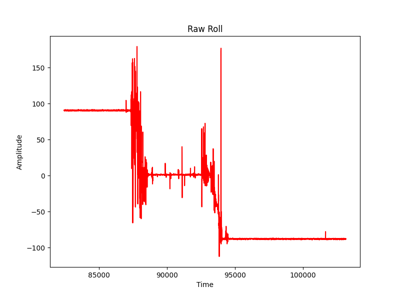
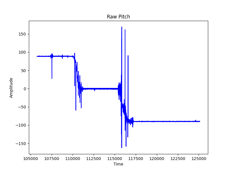
As we can see from the above pictures, it was pretty noisy data. There was a bit of
skew with the sensor data, so we had to adjust them according to these equations:
roll_a = 1.017*roll_a + 2.23;

                  pitch_a = 1.016*pitch_a -1.22264;
We then ran the
data through a Fourier Transform function.
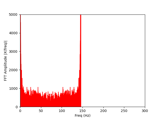
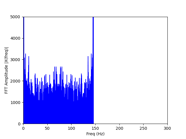
As we can see from the above pictures, we see there are large spikes near ~140Hz. Unfortunately, when calculating the alpha for the low pass filter, this gives a value of 0.9999 which is essentially no filtering. We do see there is a general flatness to the FFT graph. This is due to the internal low pass filter built into the board.
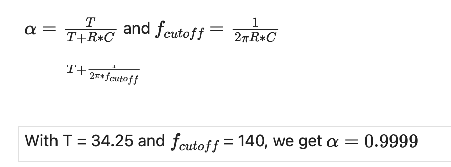
We then attempted the noisy data by tapping the table, but the FFT graph yielded similar results.
Gyroscope
The Gyroscope was used to estimate the roll, pitch, and yaw of the board. The data readings had very little noise, but were very susceptible to drift. We compare the gyroscope data to the accelerometer and then fuse the two using a complimentary filter to have more accurate readings.
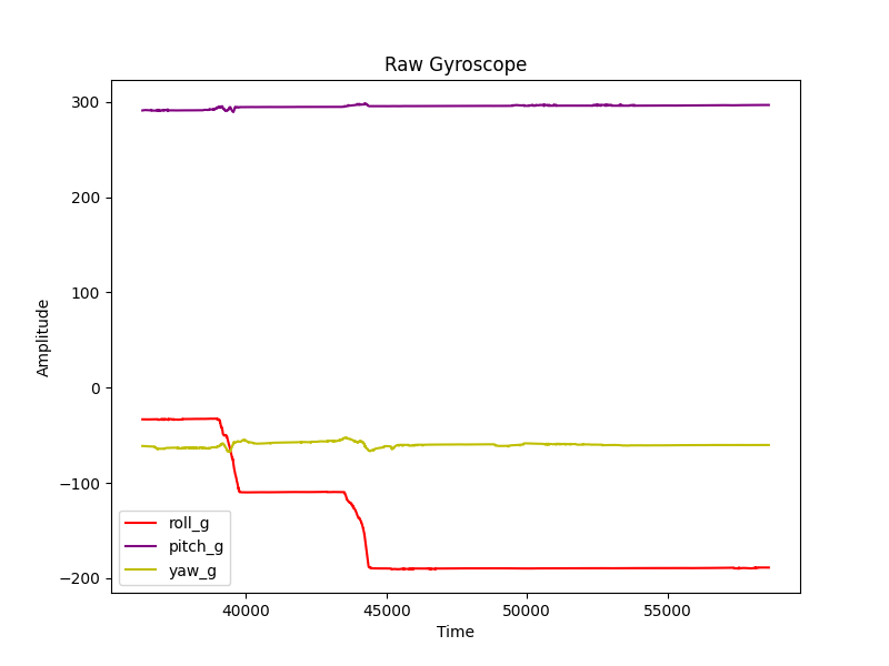
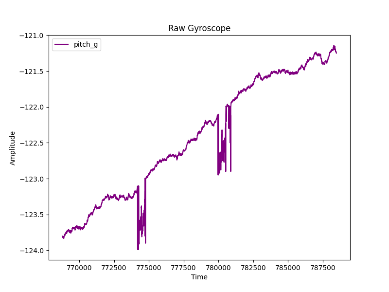
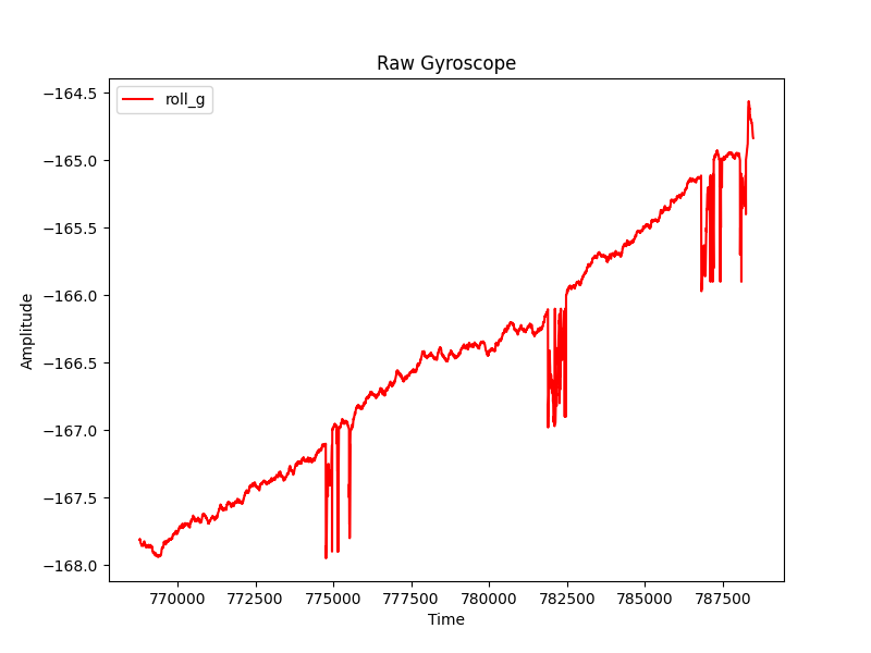
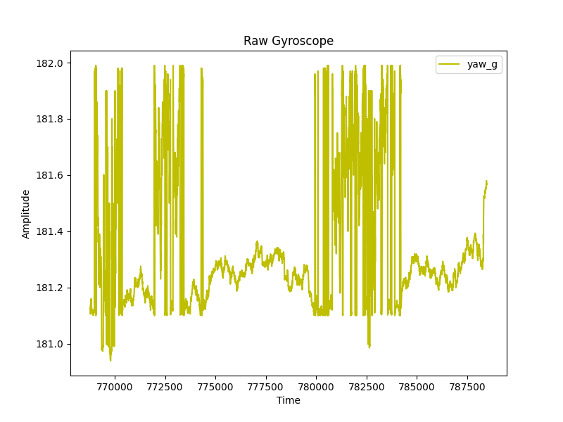
We see that the data has lttle noise, but the drift is quite large from the pitch and yaw. A noteworthy point is that the scales of the gyroscope derived angles differ from the accelerometer. This is rectified with the complimentary filter.
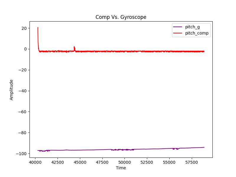
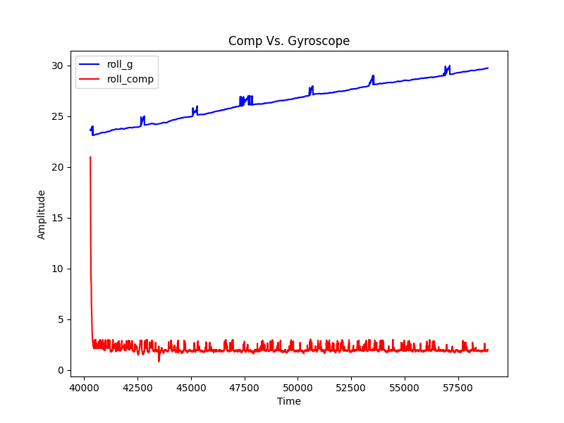
We see from the graphs that the complimentary filter (with 0.9 lending towards the gyroscope and 0.1 towards the accelerometer), does drastically decrease the drifting.
Sample Data
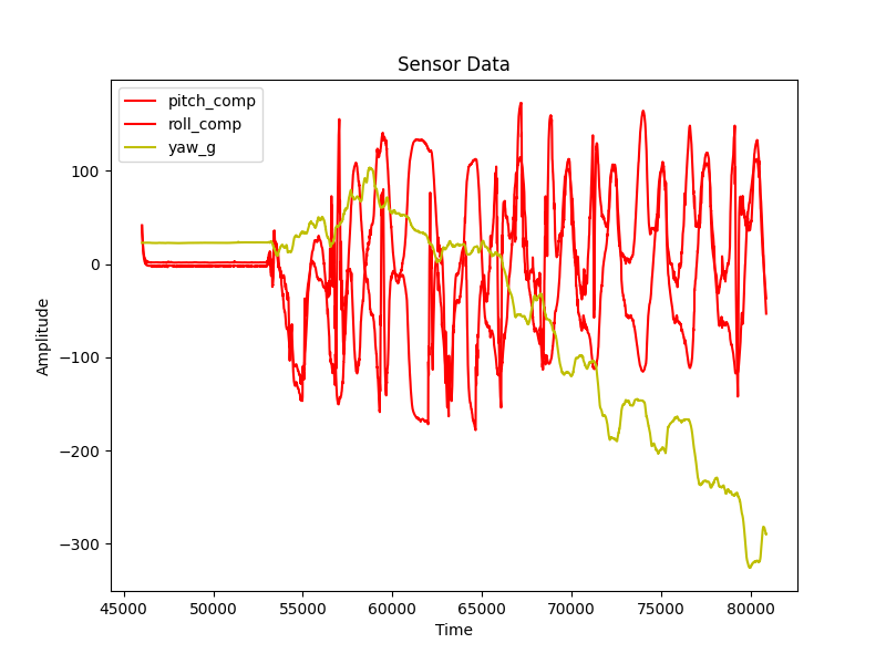
Throughout the data exploration, we had the data sampled regardless of when it was ready. This had a sample rate of ~260Hz, but there was a lot of redudant data. We then move this code into the same if statement that checks if the new data was ready. This increased the number of unique data values, but decreased our sampling rate to ~150Hz. Regardless, with an array size of 5000, we were able to collect over 30 seconds of data, which is more than enough.
Record Stunt
This portion of the lab has been removed as the board has not been mounted yet. I did test the RC robot to ensure the batteries worked and the robot would drive.